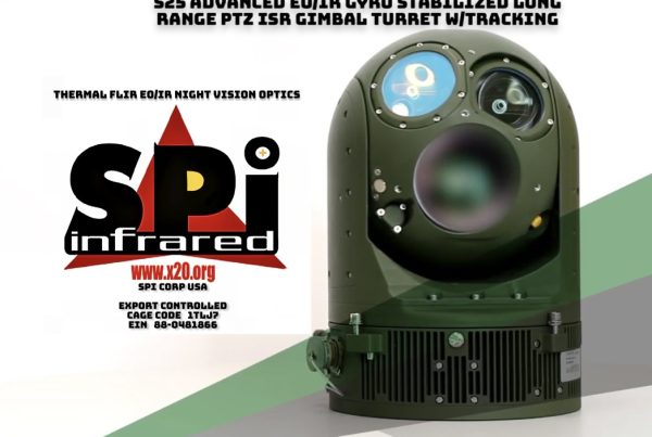
PTZ thermal imaging flir camera tracking and detection systems
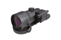
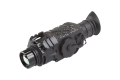
TRX9959 is an option for effective Tracking & detection used with SPI EOIR camera systems. The TRX9959 is based on a NVIDIA Jetson embedded processor which incorporates a multicore ARM processor and powerful GPU. Video interfaces are provided for HD and SD video in both analog and digital formats.
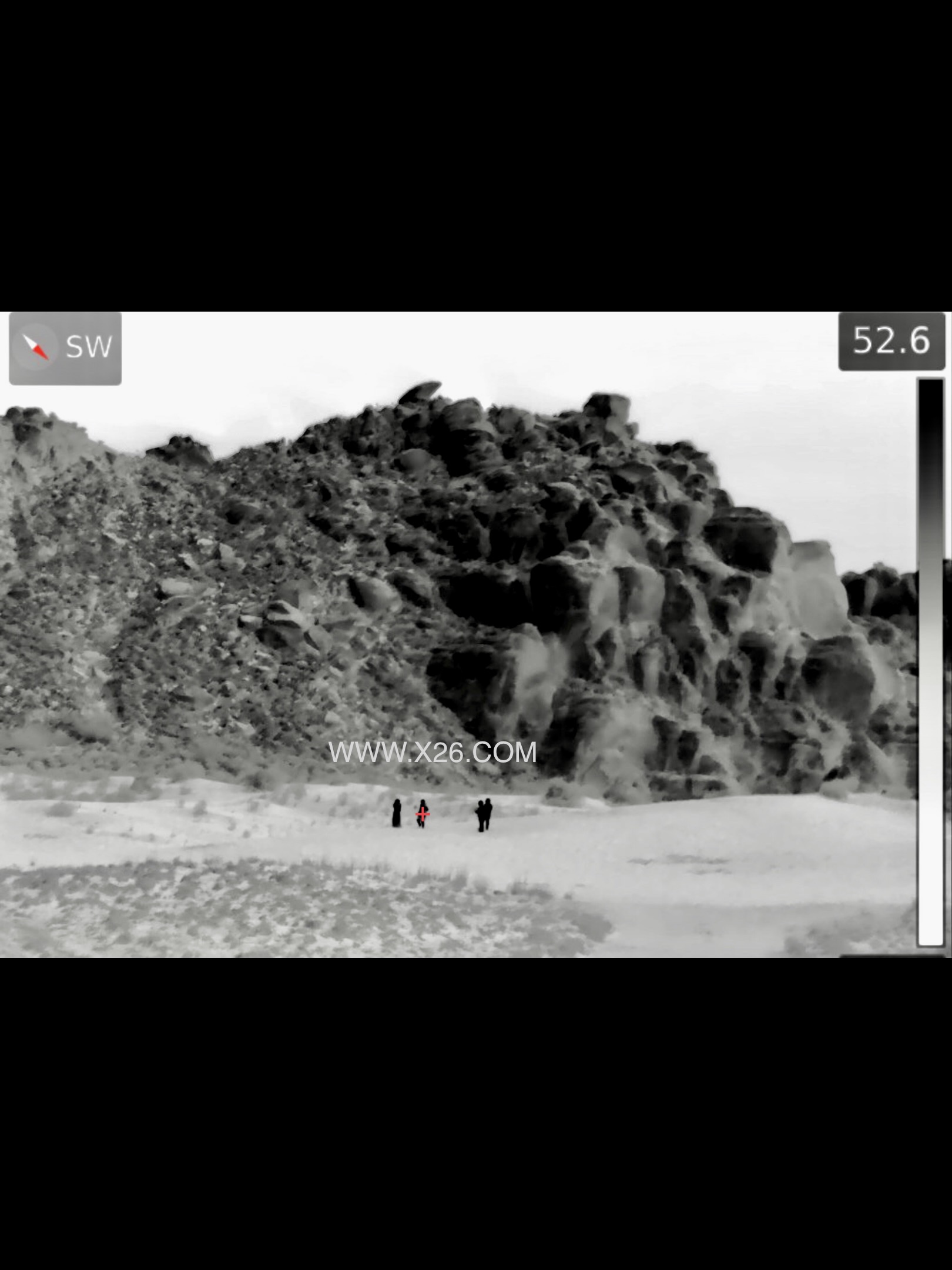
The TRX9959 offers jitter free precision pinpoint target / object tracking capabilities
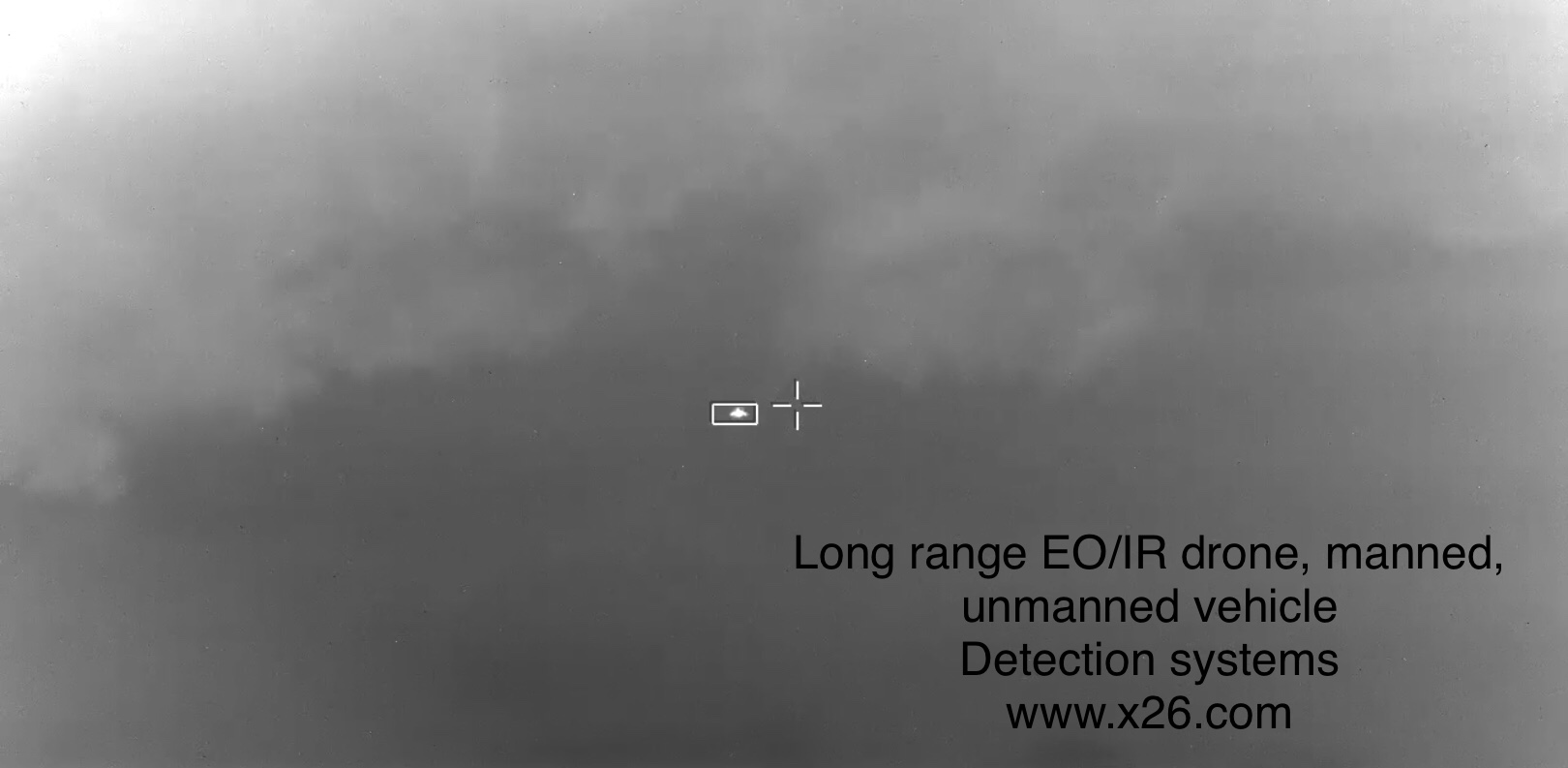
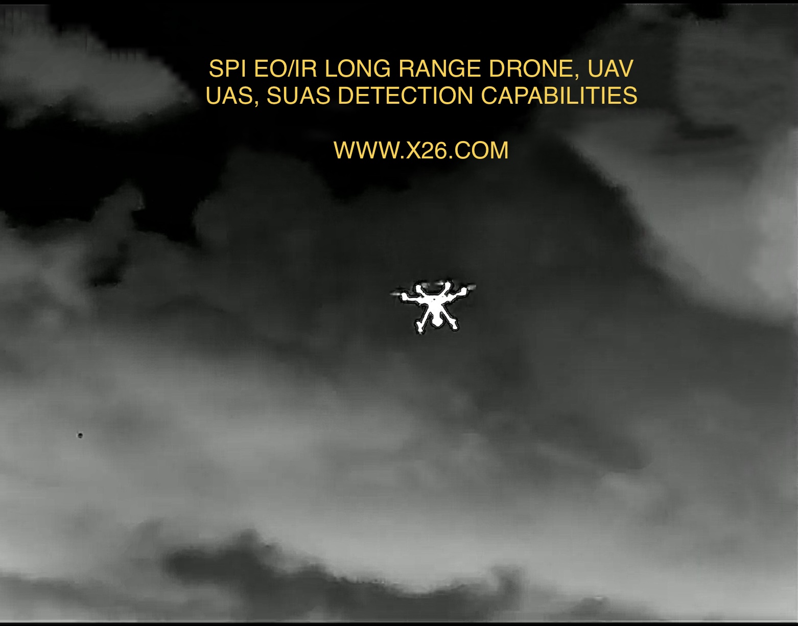
Long range thermal imaging eoir drone uav uas suas detection countermeasures IR
Video Interfaces
The TRX9959 has the following video interfaces
Video Inputs
– 2 x PAL/NTSC
– 2 x YPbPr
– 4 x SD/HD/3G SDI
Video Outputs
– 4 x PAL/NTSC/YPrPb
– 4 x SD/HD/3G SDI
Variants for CameraLink, CoaXPress and HDMI
VMS Software
The TRX9959 hosts universal VMS which is a comprehensive real time video management software suite for video and image processing. The VMS software includes the following capabilities:
• Video detection and tracking using DART library
• Video compression and recording
– H.264, M-JPEG
• Video streaming
– MPEG-TS (STANAG 4609)
– RTSP
– DEF STAN 00-82
• Electronic image stabilization
• Panoramic image formation
• Image enhancement
• Camera control
• Servo platform control
• Remote control over IP
TRX9959 Architecture
The TRX9959 uses a FPGA for high speed, low latency video interfacing and processing combined with the flexibility of the Jetson embedded processing which includes the following resources:
• Quad core ARM A57 CPU
• 256 CUDA core GPU
• Video accelerator for video encode/decode
The T 100 processes two concurrent streams of standard definition or high definition video selected from the multiple analog and digital video inputs. The output video is genlocked to the input video and is comprised of low latency video from the selected input combined with processed video and graphics from the Jetson.
Applications
• Security and surveillance
• UAV & UGV
• Manned vehicles
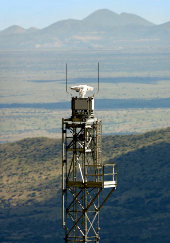
The M9 PTZ long range thermal imaging Flir camera system can be integrated with Radars for absolute slue to cue tracking capabilities
The TRX9959 is a high performance standalone video processing board. Video interfaces are provided for HD and SD video in both analog and digital formats. The primary host interface is through an Ethernet port. Multiple serial links are also provided. The Mini PCIe slot can be used to add up to 2 additional Ethernet ports.
Video Inputs
• 2 x SD analogue video inputs
– 1.0V peak to peak into 75 Ohm
– CCIR, RS170, PAL or NTSC
• 2 x HD analogue video inputs
– 1.0V peak to peak into 75 Ohm
– YPrPb
• 4 x HD digital video inputs
– SD-SDI, HD-SDI, 3G-SDI
– 480i60, 576i50, 720p50/59.94/60, 1080p25/29.97/30, 1080i50/59.94/60, 1080p50/59.94/60)
– Variants for CameraLink and HDMI
Video Outputs
• 4 x SD/HD analogue video outputs
– 1.0V peak to peak into 75 Ohm
– CCIR, RS170, PAL, NTSC or YPbPr
– Selectable symbology overlay on two outputs
• 4 x HD digital video outputs
– SD-SDI, HD-SDI, 3G-SDI
– 480i60, 576i50, 720p50/59.94/60,
– 1080p25/29.97/30,1080i50/59.94/60,
1080p50/59.94/60)
– Selectable symbology overlay on two outputs
Data Interfaces
• 1 x Ethernet
– 1000 Base-T
• 1 x Serial
– 1 x RS232
– 3 x RS422
• 1 x CANbus
Power
• 12VDC +/-5%
• <20W
Expansion
• 1 x mini PCIe slot
Mechanical
• Dimensions 100 x 100 x 20mm (3.94” x 3.94” x 0.8”)
Environmental
• Temperature
– Operating -25C to +71C
– Non-operating -40C to +85C
• Humidity
– 5% to 95% non-condensing
– Optional conformal coating available
• Shock
– 30g, 11ms
1. Scope
This document describes the software function and communication protocols used for the remote control of the SPI Video Management System (VMS) software on the
1. Scope
This document describes the software function and communication protocols used for the remote control of the SPI Video Management System (VMS) software on the Video Processor across an IP interface.
2. Product Overview
This variant of the VMS software has the following capabilities
1. Target detection and tracking
2. Video streaming over MPEG-TS
The target detection and tracking uses the DART (Detection & Acquisition, with Robust Tracking) software library.
A video tracker analyzes video image sequences from a sensor system (camera), mounted on a servo controlled pan and tilt platform to keep the camera pointing at the nominated object.
In this context the Tracker has two primary processing functions
1. Detecting and locating objects of interest in the video image (object location)
2. Controlling the Electro Optic Director (Pan and Tilt) position and rate such that the camera follows the designated object (Pan and Tilt Control)
The typical integration of the Tracker with an electro optical sensor system is shown below:
Video Tracker Electro Optic Director Display Video In 1 Video In 2 Annotated video Host System Ethernet Joystick Video Out Camera Video 1 Camera Video 2
Typical System Block Diagram Software Specification TRX 9959 Video Processor
3. Tracker Functions
3.1. Object Location
The Object Location function of the video tracker can itself be broken down into two processes, Object Detection and Object Tracking. These are mutually exclusive processes; the video tracker either detects potential objects, or tracks a single object.
To locate an object within the input video it is necessary to differentiate the object from the surrounding background. In order for the tracker to accurately and successfully perform this task the image of the object must meet certain criteria.
Initialize Object Detection Power-On BIT Acquiring Tracking Coasting Object Tracking
Figure 1 – Object Location Process Flow Software Specification TRX 9959 Video Processor
3.1.1. Object Detection
Operation
The Object Detection process starts when the tracker has completed power-on and power-on BIT. Object Detection stops when the Object Tracking process is started, see the state diagram above.
Area of Interest
The Object Detection process operates over a user defined rectangular region of the input video, the ‘Detection area of interest’. The size and position of the Detection area of interest is controlled through the tracker’s control interfaces.
Object Criteria
The Object Detection process is designed to ‘detect’ objects that meet a defined set of object criteria (e.g. size).
Object Reporting
The position and size of the highest priority object is reported in on-screen symbology and through the tracker control interfaces. The object priority metric is selectable between largest and closest to the camera Boresight.
Detection Algorithm
The following detection algorithms are available:
Manual – allows the user to manually size an inner gate within the detection window
This is a useful algorithm for targets which do not have a clearly defined bound or in a cluttered environment where the other modes do not correctly localise the target. It is very predictable and will always find something to track within the inner gate. It does, however, require that the target be centred in the field of view (FOV) and the inner gate must be suitably sized to contain the target and exclude background clutter.
Hot Spot – detects objects based on their contrast with respect to the background
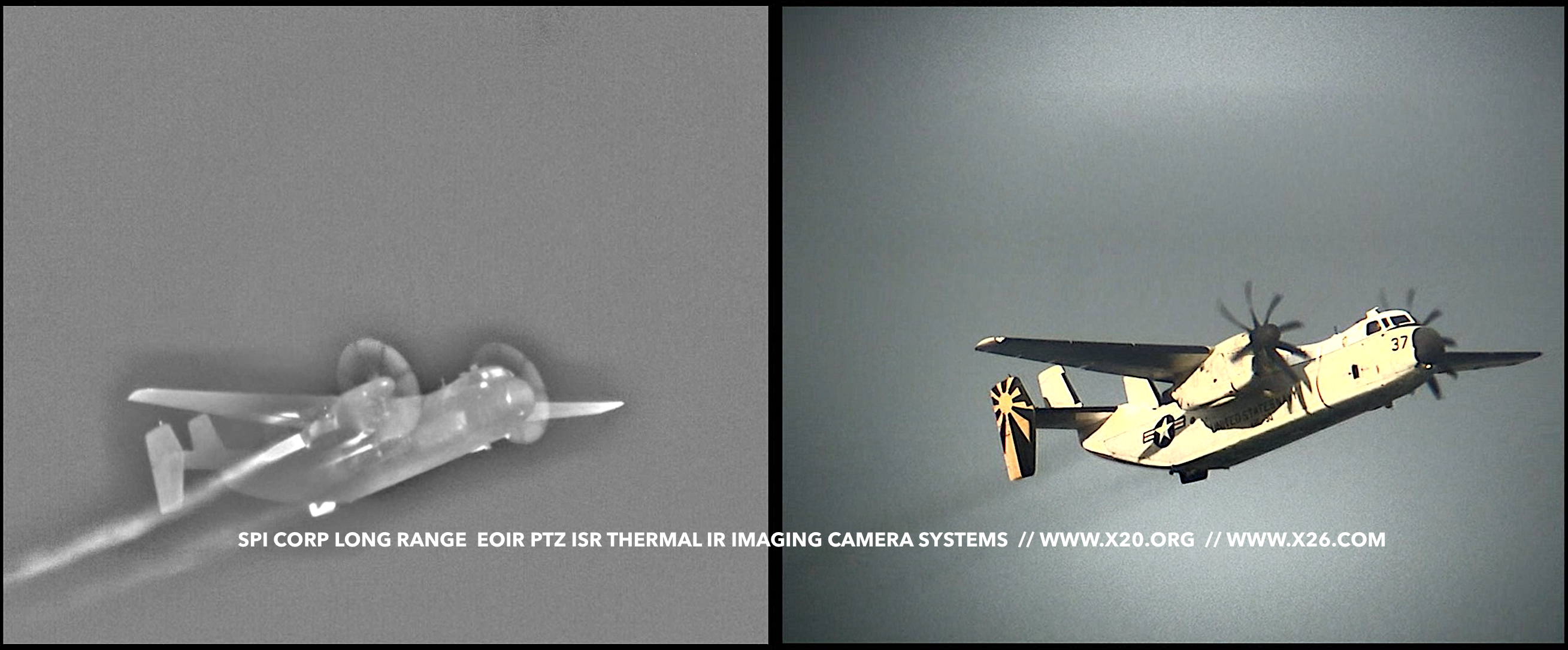
Reacts rapidly to targets entering the detection window and accurately determines target size. Works well for a wide range of target to detection window size ratios. The target must have contrast (negative or positive) with respect to any other objects or background present in the detection window. i.e., this algorithm needs bland backgrounds and little clutter. Overall this algorithm offers very good performance for high contrast targets, e.g. air targets viewed by an IR camera.
Motion – detects objects based on their motion with respect to the background
The algorithm detects objects that have either positive or negative contrast and are moving with respect to the background within the detection window. Works well in cluttered scenes, e.g. urban scenarios or those with a lot of trees etc., and with a wide range of target to detection size ratios. However, sometimes only the leading edge of a target will be detected and the requirement for movement means that it takes some time to detect targets. Good general purpose detection algorithm, especially in cluttered scenes.
Naval – contrast based detection optimised for naval targets
This is similar to the hot spot detection algorithm and detects objects that have either positive or negative contrast with respect to the background. The algorithm is optimised for the detection of small and medium size targets in a naval environment and copes well with the horizontal background gradients of horizons. Reacts rapidly to targets entering the detection window and offers particularly good performance in naval scenes viewed with IR cameras. Software Specification TRX 9959 Video Processor
3.1.2. Object Tracking
Operation
The Object Tracking process is started and stopped on command. The Object Tracking process uses object information from the Object Detection process to initiate the track. If no object has been detected when the Object Tracking process is commanded to start, the process is self-initialized based on the scene information around the centre of the Object Detection area of interest.
It is possible to configure the tracker so that the Object Tracking process is automatically started when the Object Detection process locates an object, see the state diagram above.
Area of Interest
The Object Tracking process operates over an area of interest of the input video. The size and position of the area of interest is automatically controlled by the video tracker to exclude non-target pixels from the object position calculation.
Coast
If the Tracker is unable to locate the object it was previously tracking (e.g. due to obscuration by the background), the Object Tracking process enters a search or ‘Coast’ mode. During Coast mode the Tracker uses historic target position and size information to attempt to locate and re-acquire the object. If the object is located within the defined Coast mode duration then normal Object Tracking is resumed. If the object has not been located by the end of the Coast mode duration, the Object Tracking process is then terminated and the Object Detection process started, see the state diagram below
Object Reporting
The position and size of the Tracked Object is reported in on-screen symbology and through the tracker control interfaces.
Track Algorithms
The following track algorithms are available:
Centroid – measures target positions by differentiating target pixels from background pixels based on their intensity or contrast and then calculating the centre of the target pixels.
The algorithm is designed to operate on bounded objects (blobs). It is able to estimate target size and adapt to changes in the target size. It copes well with target dynamics (acceleration etc.) and target contrast changes (e.g., due to background variations or changes in sensor gain and offset) but is susceptible to seduction by bright points in the background or target obscuration. The algorithm performs well with rapidly changing objects on bland backgrounds, e.g., aircraft with IR camera.
Correlation – measures target positions by finding the best match between a historical image of the target (pattern) and the incoming image.
The algorithm is designed to operate on objects within a complex scene or on a part of the target (such as the bridge of a large ship). It offers predictable performance and copes successfully with “coast” events caused by target obscuration. Works well on large and small targets but rapid target changes can cause the algorithm to lose track, e.g. manoeuvring aircraft. Sensor automatic gain control (AGC) changes can cause the algorithm to enter coast mode when tracking small targets and the algorithm may not be able to follow rapid target motion, e.g. elevation nod in a very narrow FOV. The algorithm exhibits very good performance on slowly changing targets, particularly those at long range (i.e. where AGC changes are slow). Software Specification TRX 9959 Video Processor
MTT – measures multiple target positions using the selected detection algorithm
For situations where multiple target tracking is required the MTT algorithm should be selected. In this mode of operation target positions are determined using the selected detection algorithm (except manual). MTT is more suited to bounded objects and performs better than the centroid algorithm in clutter.
Combined – measures target positions using a combination of centroid and correlation algorithms
The combined algorithm performs better than the correlation algorithm with rapidly changing targets and is better in clutter than the centroid algorithm. This algorithm is a good general purpose default selection especially where a variety of targets and backgrounds need to be accommodated.
Scenelock – measures motion of the whole scene using a modified large area correlation process.
The Scenelock algorithm is designed to estimate the motion of the whole scene and ignore the motion of the small targets. This algorithm is useful when trying to stabilise the motion of the electro optical system. Software Specification TRX 9959 Video Processor
4. Video coordinate system
The size of the video input depends on the particular piece of hardware being used and its video interfaces. The Tracker coordinate system uses the captured video frame as the basis of its coordinate system.
4.1. Camera Boresight
The position of the camera Boresight is defined relative to the top left of the processed video frame, using a positive right and down coordinate set. The camera processing limits are defined in the same coordinate set.
4.2. Object Position
The Tracker measures object positions by calculating the location of the object Aimpoint with respect to the Boresight position within the video frame, using a positive right and up coordinate set. The position of the Tracker area of interest is defined in the same coordinate set.
Video Frame Camera Boresight Object Aimpoint Object Location Y Object Location X Boresight Position X Boresight Position Y
Figure 2 – Object Location calculation
| The exact definition of the object Aimpoint is dependent on the Object Track algorithm selected: TRACK ALGORITHM | AIMPOINT |
| Centroid | Target center |
| MTT | Target center |
| Correlation | Match position |
| Combined | Target centre or match position |
| Scenelock | Scene center |
Video Processor across an IP interface.
2. Product Overview
This variant of the VMS software has the following capabilities
1. Target detection and tracking
2. Video streaming over MPEG-TS
The target detection and tracking uses the DART (Detection & Acquisition, with Robust Tracking) software library.
A video tracker analyzes video image sequences from a sensor system (camera), mounted on a servo controlled pan and tilt platform to keep the camera pointing at the nominated object.
In this context the Tracker has two primary processing functions
1. Detecting and locating objects of interest in the video image (object location)
2. Controlling the Electro Optic Director (Pan and Tilt) position and rate such that the camera follows the designated object (Pan and Tilt Control)
The typical integration of the Tracker with an electro optical sensor system is shown below:
Video Tracker Electro Optic Director Display Video In 1 Video In 2 Annotated video Host System Ethernet Joystick Video Out Camera Video 1 Camera Video 2
3. Tracker Functions
3.1. Object Location
The Object Location function of the video tracker can itself be broken down into two processes, Object Detection and Object Tracking. These are mutually exclusive processes; the video tracker either detects potential objects, or tracks a single object.
To locate an object within the input video it is necessary to differentiate the object from the surrounding background. In order for the tracker to accurately and successfully perform this task the image of the object must meet certain criteria.
Initialize Object Detection Power-On BIT Acquiring Tracking Coasting Object Tracking
Figure 1 – Object Location Process Flow Software Specification
3.1.1. Object Detection
Operation
The Object Detection process starts when the tracker has completed power-on and power-on BIT. Object Detection stops when the Object Tracking process is started, see the state diagram above.
Area of Interest
The Object Detection process operates over a user defined rectangular region of the input video, the ‘Detection area of interest’. The size and position of the Detection area of interest is controlled through the tracker’s control interfaces.
Object Criteria
The Object Detection process is designed to ‘detect’ objects that meet a defined set of object criteria (e.g. size).
Object Reporting
The position and size of the highest priority object is reported in on-screen symbology and through the tracker control interfaces. The object priority metric is selectable between largest and closest to the camera Boresight.
Detection Algorithm
The following detection algorithms are available:
Manual – allows the user to manually size an inner gate within the detection window
This is a useful algorithm for targets which do not have a clearly defined bound or in a cluttered environment where the other modes do not correctly localise the target. It is very predictable and will always find something to track within the inner gate. It does, however, require that the target be centred in the field of view (FOV) and the inner gate must be suitably sized to contain the target and exclude background clutter.
Hot Spot – detects objects based on their contrast with respect to the background
Reacts rapidly to targets entering the detection window and accurately determines target size. Works well for a wide range of target to detection window size ratios. The target must have contrast (negative or positive) with respect to any other objects or background present in the detection window. i.e., this algorithm needs bland backgrounds and little clutter. Overall this algorithm offers very good performance for high contrast targets, e.g. air targets viewed by an IR camera.
Motion – detects objects based on their motion with respect to the background
The algorithm detects objects that have either positive or negative contrast and are moving with respect to the background within the detection window. Works well in cluttered scenes, e.g. urban scenarios or those with a lot of trees etc., and with a wide range of target to detection size ratios. However, sometimes only the leading edge of a target will be detected and the requirement for movement means that it takes some time to detect targets. Good general purpose detection algorithm, especially in cluttered scenes.
Naval – contrast based detection optimised for naval targets
This is similar to the hot spot detection algorithm and detects objects that have either positive or negative contrast with respect to the background. The algorithm is optimised for the detection of small and medium size targets in a naval environment and copes well with the horizontal background gradients of horizons. Reacts rapidly to targets entering the detection window and offers particularly good performance in naval scenes viewed with IR cameras.
3.1.2. Object Tracking
Operation
The Object Tracking process is started and stopped on command. The Object Tracking process uses object information from the Object Detection process to initiate the track. If no object has been detected when the Object Tracking process is commanded to start, the process is self-initialized based on the scene information around the centre of the Object Detection area of interest.
It is possible to configure the tracker so that the Object Tracking process is automatically started when the Object Detection process locates an object, see the state diagram above.
Area of Interest
The Object Tracking process operates over an area of interest of the input video. The size and position of the area of interest is automatically controlled by the video tracker to exclude non-target pixels from the object position calculation.
Coast
If the Tracker is unable to locate the object it was previously tracking (e.g. due to obscuration by the background), the Object Tracking process enters a search or ‘Coast’ mode. During Coast mode the Tracker uses historic target position and size information to attempt to locate and re-acquire the object. If the object is located within the defined Coast mode duration then normal Object Tracking is resumed. If the object has not been located by the end of the Coast mode duration, the Object Tracking process is then terminated and the Object Detection process started, see the state diagram below
Object Reporting
The position and size of the Tracked Object is reported in on-screen symbology and through the tracker control interfaces.
Track Algorithms
The following track algorithms are available:
Centroid – measures target positions by differentiating target pixels from background pixels based on their intensity or contrast and then calculating the centre of the target pixels.
The algorithm is designed to operate on bounded objects (blobs). It is able to estimate target size and adapt to changes in the target size. It copes well with target dynamics (acceleration etc.) and target contrast changes (e.g., due to background variations or changes in sensor gain and offset) but is susceptible to seduction by bright points in the background or target obscuration. The algorithm performs well with rapidly changing objects on bland backgrounds, e.g., aircraft with IR camera.
Correlation – measures target positions by finding the best match between a historical image of the target (pattern) and the incoming image.
The algorithm is designed to operate on objects within a complex scene or on a part of the target (such as the bridge of a large ship). It offers predictable performance and copes successfully with “coast” events caused by target obscuration. Works well on large and small targets but rapid target changes can cause the algorithm to lose track, e.g. moving aircraft. Sensor automatic gain control (AGC) changes can cause the algorithm to enter coast mode when tracking small targets and the algorithm may not be able to follow rapid target motion, e.g. elevation nod in a very narrow FOV. The algorithm exhibits very good performance on slowly changing targets, particularly those at long range (i.e. where AGC changes are slow). Software Specification
MTT – measures multiple target positions using the selected detection algorithm
For situations where multiple target tracking is required the MTT algorithm should be selected. In this mode of operation target positions are determined using the selected detection algorithm (except manual). MTT is more suited to bounded objects and performs better than the centroid algorithm in clutter.
Combined – measures target positions using a combination of centroid and correlation algorithms
The combined algorithm performs better than the correlation algorithm with rapidly changing targets and is better in clutter than the centroid algorithm. This algorithm is a good general purpose default selection especially where a variety of targets and backgrounds need to be accommodated.
Scenelock – measures motion of the whole scene using a modified large area correlation process.
The Scenelock algorithm is designed to estimate the motion of the whole scene and ignore the motion of the small targets. This algorithm is useful when trying to stabilise the motion of the electro optical system. Software Specification
4. Video coordinate system
The size of the video input depends on the particular piece of hardware being used and its video interfaces. The Tracker coordinate system uses the captured video frame as the basis of its coordinate system.
4.1. Camera Boresight
The position of the camera Boresight is defined relative to the top left of the processed video frame, using a positive right and down coordinate set. The camera processing limits are defined in the same coordinate set.
4.2. Object Position
The Tracker measures object positions by calculating the location of the object Aimpoint with respect to the Boresight position within the video frame, using a positive right and up coordinate set. The position of the Tracker area of interest is defined in the same coordinate set.
Video Frame Camera Boresight Object Aimpoint Object Location Y Object Location X Boresight Position X Boresight Position Y
Figure 2 – Object Location calculation
| The exact definition of the object Aimpoint is dependent on the Object Track algorithm selected: TRACK ALGORITHM | AIMPOINT |
| Centroid | Target Center |
| MTT | Target center |
| Correlation | Match position |
| Combined | Target centre or match position |
| Scenelock | Scene center |
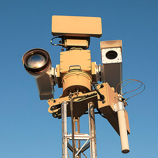
With Long range PTZ or pan / tilt / zoom radar integrated thermal imaging becoming an integral part of Short, medium, long and extreme ultra long range radar assisted Surveillance, security, observation systems, a whole range of uses becomes both possible and economically viable. long range Thermal flir PTZ cameras with radar can be an excellent complement in many situations where conventional cameras diminish their performance as low light levels are present. They are, of course, unparalleled in a situation of twilight, thermal cross-over, near darkness and total darkness. They can also be an option in areas that are very difficult to illuminate effectively, for example a sea front, a harbor, or any other vast expanse of open water thus making SPI’s long range PTZ thermal infrared imaging Ir cameras paramount for use in marine, boat, vessel and ship applications. Similarly, artificial light not only runs the risk of revealing where the cameras are placed, enabling parties to avoid or vandalize them, but can also create projected shadows in which an intruder can avoid detection. Furthermore, spotlights can blind as well as illuminate. So cameras that do not rely on light can be the preferred solution in many different traffic situations, whether it is in railway tunnels, on air strips, runways, or on regular streets. Long Range radar Thermal flir PTZ cameras, on the other hand, cannot be blinded by bright lights or laser beams. SPI Corp’s long range multi sensor radar enabled Eoir flir thermal imaging camera systems offer substantial long distance detection ranges allowing the operator to be positioned at very far distant standoff locations offering ample time to react, to threats or targets of interest. Long range imaging systems provide a benefit to the user when coupled with an array of sensors and geo locating modules especially in specialty military, security and surveillance applications. The farther you are, the more time you have to react and not be seen. What the science behind a radar coupled long range thermal imaging FLIR IR night vision PTZ pan tilt gimbal turret camera / Housing – Usually composed of an aluminum bell shaped cover, The housing can be of all shapes and sizes from plastic to military grade hardened coated all weather NBC Nuclear Biological Chemical compliant
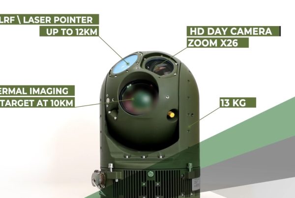
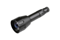
Camera module
This is where the high definition HD GSR (Ground Surveillane Radar) range FLIR, MWIR, LWIR, SWIR, night vision, LLL, Low Light Level, intensified, cmos, long wave, short wave, mid wave cooled and uncooled detector and sensors reside, CCD sensor, optical zoom germanium DFOV, TFOV, Fixed and CZ continuous zoom lenses, and the motors that control Zoom and Focus are located.
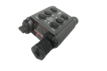
PTZ Pan Tilt control board
The PTZ control board processes remote (IP, Network, RJ45, ETHERNET) RS485 data that converts it into mechanical movements. Some are Pelco, Pelco Extended and are available in a wide array of protocols supporting VMS, GUI, ONVIF, IP, ETHERNET, FIBER, MICROWAVE, ANALOG, DIGITAL and WIRELESS
Pan tilt zoom PTZ motors – are the small motors that allow the radar long range thermal HD FLIR and long distance CCTV HD camera to perform up, down, left and right functions. Marked by the arrows are two step motors; the one to the top controls up and down movements and the one at the bottom controls left and right movements, some systems have no motors and other methods of moving the long range flir cameras PTZ, some use brushless motors.We can Customize your long range Pan Tilt Zoom Thermal, CCTV and other exotic sensor system to cater to your exact application,
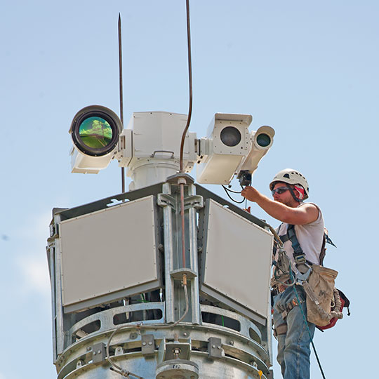
We have facilities that can satisfy any requirement in a rapid response timeframe. We offer the worlds longest range, best weapons grade all weather IP68 hardened PTZ EOIR
imaging systems. Contact us for additional information and pricing or call 702-499-9551. Long Range radar Visible HD CCTV cameras can compliment the Thermal cameras and assist in daytime and low light DRI (Detection, Recognition and Identification)Long range Critical infrastructure applications require not only continuous video surveillance and monitoring, but also a solution that yields highly reliable intrusion detection, with fewer false alarms. This need makes advanced video analytics a must for any adequate long range thermal/cctv surveillance system.Advanced analytics will provide multiple automated alarm notification options, including email, edge image storage, digital outputs or video management software (VMS) alarms. Incorporating high quality, unique and adaptive analytics can virtually eliminate false alarms, allowing security personnel to respond more efficiently and effectively, while also lowering overall cost for the end user.While traditional long range surveillance & security technologies such as radar, thermal flir imaging and visible cameras, or video analytics work well on their own, utilizing all of these options together provide an advanced perimeter detection system. For example, ground surveillance radar can detect possible threats beyond the fence line as they approach and send a signal to pan-tilt-zoom (PTZ) cameras, triggering them to slew to a specific location. From there, embedded analytics and visible cameras can further identify objects, notify authorized staff, and collect additional evidence through facial recognition or high-quality photos. Once a long range intrusion attempt is discovered, it is important to act fast. Organizing a response system that can initiate actions based on GPS location data, such as the slewing of radar long range FLIR PTZ cameras, automated intruder tracking or activated lighting sensors, greatly increases staff’s situational awareness while easing their workload. For instance, HD long range thermal imagers deployed in conjunction with video analytics can be used to generate an initial alarm event, which can then trigger a sequence of other security equipment and notifications for personnel to eventually respond to. Having all of this in place essentially lays the entire situation out in a way that allows responders to accurately understand and evaluate a scene.After the designated auto-response mechanisms have activated and done their job, it is time for responders to acknowledge and assess the situation. From here, authorized personnel can take the next appropriate step toward defending against and delaying the threat. Deterring suspicious activity can be achieved through real-time two-way audio, a simple but powerful tool. Often, control room operators can diffuse a situation by speaking over an intercom, telling the trespasser that they are being watched and that the authorities have been notified.The primary purpose of the delay facet of the overall perimeter protection strategy is to stall an attempted intrusion long enough for responders to act. Access control systems play a key role in realizing this objective. When a security officer sees a non-compliant, suspicious individual on the camera feed, the officer can lock all possible exits to trap them in one area all through the VMS.
See clearly also in broad daylight and in total darkness night vision
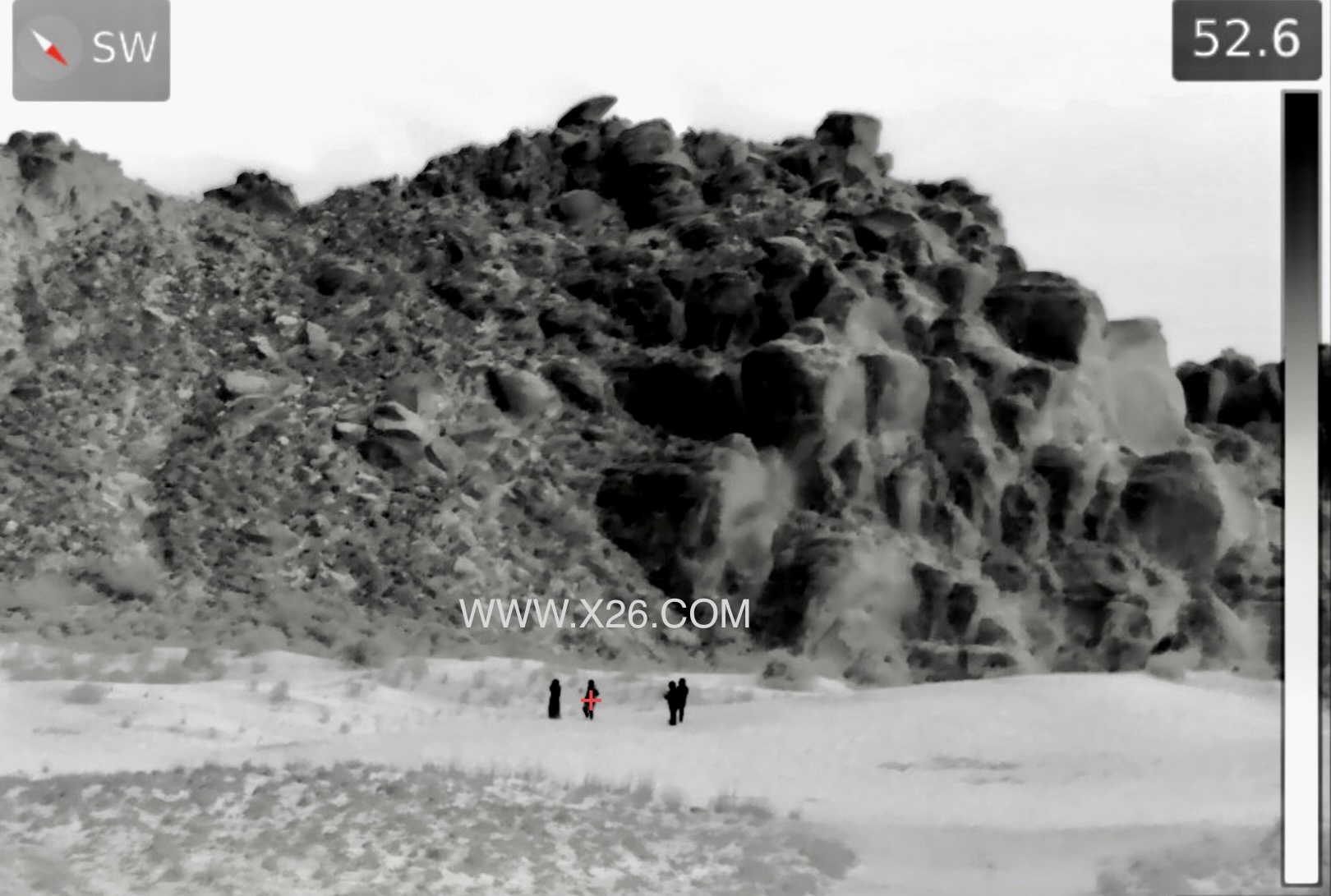
SPI’s long range IR FLIR PTZ pan tilt thermal imaging cameras will not only protect borders and assets against intruders during the darkest of nights. The coupling of a Radar add an extra layer of tracking and detection capabilities, The cameras are also perfectly suited for daytime surveillance. The radar long range infrared cooled and uncooled FLIR thermal imaging cameras will detect objects that remain invisible to the naked eye. For example, people hiding in the shadows or in the bushes will be detected. The cameras are also not blinded by glare from the sun.
Force Protection, Border Security and Surveillance The Ultra extreme NFOV long range FLIR thermal imaging night vision PTZ surveillance systems cover more territory and enable detection and classification better than any other sensor suite available. Networkable video and control make the long range FLIR thermal imaging systems the perfect border security imaging solution. The systems can be connected to a radar in a so called “slew to cue” configuration. If the radar detects an object, the camera turns in the correct direction so that you get a visual image from that blip on your radar screen.
Radar Coastal Surveillance in some countries are bordered by thousands of kilometers of coastline. The long range ptz pan tilt zoom FLIR radar thermal imaging systems are the perfect tools to monitor what is happening along the coastline. They can be used to intercept illegal immigrants or to detect other threats coming from the sea. They are perfect for Vessel Traffic Monitoring and can work together with Automatic Identification Systems (AIS) and Ground surveillance radars.
Radar assisted Perimeter Security Airports, air force bases, hydroelectric power plants, refineries, oil and gas pipelines and any other large infrastructure objects have perimeters that can be kilometers long. The ultra extreme FLIR radar thermal imaging systems provide the ultimate security solution. Detection ranges can exceed 50 kilometers KM
Quick and accurate Pan & Tilt unit The ultra compact, ultra precision IP68+ Pan & Tilt unit is designed for heavy duty service in extremely demanding environments, from hot desert to arctic conditions. This positioning unit includes slip-ring connections for the different signals (video, power and data), which allow for infinite horizontal rotation, and provide DC servo drives for the rotary movement in both axes. High precision gears provide fast accurate movement, free from backlash and extremely low hysteresis, through a continuous 360° rotation. The performance contributes to find targets faster, as well as to get a good and stable display of the sensors’ pictures even in very narrow fields of view. Incremental encoders allow for accurate geo-referencing of targets with precise read-out of the vertical and horizontal angles. Our radar assisted PTZ pan tilt gimbals are the longest lasting most reliable positioning gimbals available. Enhanced electronic and active gyro stabilization ensures jitter free imagery at extreme long ranges and while operating the system on the move on mobile/windy harsh mast/pole/tripod hydraulic and retractable platforms.
Laser Range Finder LRF, SPI’s ultra extreme long range day/night vision MWIR midwave cooled and long-wave LWIR uncooled systems can be equipped with long range eye safe Laser Range Finder. Combined with the GPS system and the electromagnetic compass, it will allow you to exactly determine where a suspected object is located and how far it is away even at extreme standoff long ranges.
Easy to install learn and operate, Our long range thermal radar IR infrared imaging PTZ pan tilt gimbal systems are designed to be easily installed and operated from remote or local C2.