THE HISTORY OF NIGHT VISION AND THERMAL IMAGING FLIR TECHNOLOGIES EXPLAINED, APPLICATIONS + USES
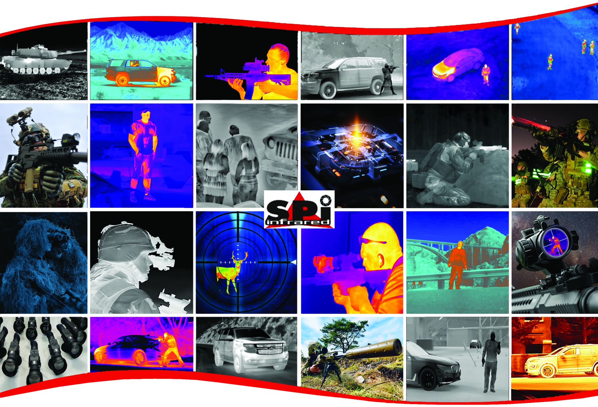
SAMPLE THERMAL FLIR IMAGING AND NIGHT VISION
TECHNOLOGY PRODUCT LINKS ARE LISTED BELOW
This Night Vision and thermal imaging FLIR (Forward Looking InfraRed) Technologies resource page is for military, emergency responders, law enforcement, and security professionals with a reference on night vision technologies, capabilities, and limitations. This data provides introductory-level information on the technologies and components for night vision devices (NVDs), as well as an overview of their applications..
Here we look at thermal flir imaging and NVDs technologies for applications that include law enforcement, natural resource management, fire and rescue, emergency management, engineering, medical, and security services. The devices described include the following:
- · Image intensifiers (I2);
- · Thermal imaging cameras;
- · Integrated night vision systems (INVSs); and
- · Near infrared (NIR) illuminators.
A COMPREHENSIVE THERMAL INFRARED FLIR IMAGING AND NIGHT VISION
IMAGE GALLERY LINK IS AVAILABLE HERE
(Heavy image page, may take a moment to load)
A night vision device (NVD) is an electro-optical
device that enhances vision in environmental
conditions with little or no light. Since World
War II, NVDs have been used by military
organizations as a force multiplier, greatly
extending military operational capabilities in
nighttime or low-light scenarios. NVD
technology is used by many non-military
agencies, such as law enforcement, fire, and
search and rescue. NVDs include Image
Intensifier (I2) devices, thermal imaging cameras,
integrated night vision systems (INVSs), and
near infrared (NIR) illuminator technology. An
example of an I2 display is shown in 1-1. NVDs can enhance almost any emergency response agency’s operational capability by enabling the user to perform one or more of the following functions:
- · Detection–detect an object in limited light;
- · Recognition–recognize the object; and
- · Identification–identify distinguishing features.
A brief review of the electromagnetic spectrum and a history of NVDs are provided to assist in understanding how NVDs can enhance night operation capabilities.
1.1 The Visible Light Spectrum
Visible light represents a narrow band of the greater electromagnetic spectrum, 1-2. The visible spectrum contains all colors from violet to red. Each of the colors in the visible spectrum has its own characteristic wavelength. The wavelengths of visible light correspond to a range between approximately 400(violet) and 700 (red) nanometers (nm). It is the reflection of light within the visible wavelength that results in objects appearing in color to the human eye. For example, objects appear green because all of the other observable color wavelengths are absorbed by the objects surface except for green, which is reflected.
1-2. Visible Light and Infrared in the Electromagnetic Spectrum
1-1. I Display
NVDs are sensitive to sections of the electromagnetic spectrum, commonly called bands or frequency bands, which are outside the range of human vision. NVD technology utilizes a specific portion of the electromagnetic spectrum as defined by the NVD industry and depicted in 1-2.
1.2 History of Night Vision Technology
Night glasses were one of the first NVDs developed. They were simple optical devices, similar to binoculars or a telescope, with large diameter objective lenses. Night glasses, such as those seen in 1-3, had 55 millimeter (mm) or larger objective lenses and at least 7x magnification. They were heavy and often dangerous to use because the pupil reflex of the eye is not fast enough to prevent damage from sudden exposure to a large amount of light.
1.2.1 Development of image Intensification
1-3. Night Glasses
Other products developed during World War II include the cascade image tube and the infrared illuminator. Initial development efforts of I2 NVDs depended on active infrared illumination of a target in order to operate. In combat or surveillance, active illumination devices have limited usefulness, because they can reveal the source of light to an adversary using a device capable of seeing infrared. These technologies are explained in more detail in Section 2.1.
The I2 technology as it existed then is known as Generation 0 (Gen 0) I2. The U.S. military used this type of device during the Korean War.
The first passive military I2 NVDs were used during the Vietnam War. These Generation 1 (Gen 1) I2 NVDs are known as starlight scopes as they used ambient light from the moon and stars to enhance available lighting. These devices were bulky and cumbersome, but since they did not use any additional illumination (i.e., infrared), the user’s location was not revealed. An example of a Gen 1 starlight scope is shown in 1-4.
1-4. Gen 1 Starlight Scope
Produced in the 1980s, Generation 2 (Gen 2) I2 NVDs provided substantial improvements in performance and packaging. Performance was improved by the addition of a microchannel plate (MCP) to the image-intensifier tube. The MCP resulted in images that were less distorted and brighter than earlier-generation NVDs. The reduction in size and weight permitted the device to be attached to a helmet or other headgear. Gen 2 devices are the most commonly available I2 NVDs due to their record of performance and low relative cost.
Generation 3 (Gen 3) I2 NVDs were developed in the late 1980s, and were used extensively during the Gulf War in 1991. This generation NVD provided more light amplification and a longer service life than the prior generation NVDs. Gen 3 devices that amplify low ambient light levels by 30,000 to 50,000 times are becoming more commonplace outside military applications.
1.2.2 Development of Thermal Imaging Cameras
Thermal imaging cameras allow users to see the thermal infrared radiation emitted by objects. The infrared energy radiated from objects depends on the objects’ temperatures and the difference in temperatures can be seen as different colors or shades of gray. As these cameras do not use light, they are effective even in total darkness.
The development of the thermal imaging camera (also known as a thermal imager) began in the late 1960s as an aid to air navigation. Customizing thermal imaging cameras for use in other military applications began in the 1970s. The first commercial thermal imagers became available in the 1980s. In the 1990s, thermal imaging sensor technology enhancements included greater sensitivity and higher resolution. Since then, thermal imaging cameras have found broad acceptance in law enforcement, fire and rescue, engineering, medical services, and the security industry (see 1-5).
1-5. Firefighter Using a Thermal Imaging Camera
Photo Courtesy of National Fire Academy
- NIGHT VISION TECHNOLOGY REVIEWS
There are advantages and disadvantages associated with each type of NVD technology. As briefly discussed in Section 1, all NVDs can enable a user to perform three basic functions—detection, recognition, and identification—to some degree, in low or no light conditions. The same scene in daylight and using NVD technologies can be seen in 2-1.
Digital Day Image Thermal Night Image I2 Night Image 2-1. Multiple Technologies Scene Displays
2.1 Image Intensification
I2 devices use light-amplifying technology that requires minimal light to operate. These devices are produced as monoculars, binoculars, goggles, and riflescopes. I2 technology is generally categorized within four generations as established by the U.S. Army’s Night Vision and Electronic Sensors Directorate (NVESD). These generations are based on the components and level of sophistication of the image intensification technology and include: Gen 0, Gen 1, Gen 2, and Gen 3. Some manufacturers have expanded the designations to include Generation 2 plus (Gen 2+), Generation 3 plus (Gen 3+) and Generation 4 (Gen 4), though these are not included in the NVESD categorizations.
2.1.1 Operating Principle
I2 devices use components known as photomultiplier tubes to enable visibility in very low-light scenarios. The overall operating principle for Gen 2 and 3 photomultiplier tubes is illustrated in 2-2. The photomultiplier tubes use a lens to collect available light, including light from the infrared portion of the spectrum. Once past the lens, the light strikes the photocathode which causes the release of an electron.
2-2. Gen 2 and Gen 3 Photomultiplier Tube Operating Principle
The electrons travel through the tube, accelerating towards another plate and causing a cascade effect that increases the number of electrons. These electrons strike a screen coated with a phosphorescent compound that will glow 2-3.
When using an I2 NVD, the operator views the scene through an ocular lens that focuses the image. A separation between the ocular lens and the eye, known as eye relief distance, is necessary.
Many types of phosphor screens are available on I2 devices, with the
most common being designated P22 (green), P43 (yellow-green), and
P45 (white). The P22 screen is the most commonly used, and is the popular choice for military and law enforcement due to the wider visible spectrum. The P43 screen has a narrower visible spectrum and has become popular among aviators for its fast decay time (i.e., the time it takes for the image to fade on the screen). The P45 screen provides similar decay times to P43, with excellent recognition capability. The image presented to the user of a P45 screen is black and white, which results in less eye fatigue, faster recognition (especially in sandy/rocky terrain), and a slightly better discrimination of shades of intensity than the traditional green.
2-3. I2 Display
2.1.2 Image Intensifier Technologies
As discussed in Section 1.1, night glasses were the earliest passive NVD and employed a large objective lens that captured available light (photons) and condensed that light into a much smaller area.
2.1.2.1 Generation 0 Image Intensifiers
I2 Gen 0 technology used active NIR illumination that cannot be seen by the human eye. In a Gen 0 system, invisible light from an infrared illuminator reflected off objects in the scene and back to the objective lens of the NVD, 2-4. The sensor element employed a control grid between the photocathode and the phosphor screen to accelerate the flow of electrons toward the phosphor screen. This acceleration process caused premature deterioration of the tube, reducing its useable service life and somewhat distorting the image. Gen 0 NVDs are no longer available on the commercial or military market.
2.1.2.2 Generation 1 Image Intensifiers
I2 NVD technology shifted to passive infrared in
Gen 1 NVDs. 2-5, Gen 1 NVDs use essentially the same intensifier tube configuration as
Gen 0 devices. They also have the same image distortion and short service life issues experienced with Gen 0 NVDs.
The major advantage of Gen 1 NVDs over Gen 0 devices is that Gen 1 devices do not require an illumination source but instead use available visible and infrared light.
Gen 1 NVDs have some undesirable characteristics, including a high-pitched whine when they are initially powered on, a slightly distorted image, and a tendency to continue producing a green glow after being powered down.
2.1.2.3 Generation 2 Image Intensifiers
2-4. Gen 0 NVD
Image distortion and reduced service life issues in previous generations of I2 NVDs led to the development of the microchannel plate (MCP). This small glass disc, 2-6, is typically one inch in diameter and has an electrode on both sides to attract and control the flow of electrons. The MCP, as illustrated in 2-7, greatly increases the number of electrons that reach the phosphor screen, enabling effective observation with less light than earlier generations.
2-5. Gen 1 NVD
The MCP Gen 2 NVDs require much less power than their predecessors, and are effective in very low-light conditions.
2-6. Gen 2 NVD 2-7. Microchannel Plate
2.1.2.4 Generation 3 Image Intensifiers
Gen 3 NVDs are similar to Gen 2, except that the photocathode is composed of gallium arsenide. This material is highly sensitive to NIR light and forms an image regardless of the degree of illumination in the visible light spectrum by significantly amplifying the number of electrons in the intensifier tube. In addition, the intensifier tube is coated with an ion barrier that substantially increases the service life of the intensifier tube compared to Gen 2 tubes.
Reduced electron flow at the ion barrier may cause a loss of brightness and mild image distortion in some Gen 3 NVDs. To counter this effect, some manufacturers have removed the ion barrier in order to increase brightness and resolution. A second improvement resulted from the use of an automatic gated power supply, which regulates the photocathode voltage as lighting conditions change. Some manufacturers call this Gen 3+ or Gen 4 in their literature, but these designations have not been adopted by the military. The accepted nomenclature for this technology is “filmless and gated.” Filmless and gated devices have improved Gen 3 NVD performance in both extremely low-light and bright-light environments. Gen 3 devices are usually powered by AA batteries or a 3-volt CR-123 battery that provides approximately
40 hours of operation. The projected tube life of a Gen 3 device is 10,000 hours. The system electronics of these devices also feature protective circuits to prevent damage to the intensifier tube and guard against undesirable effects in the visual image, such as blooming and haloing. These terms are described in Section 4.2.5.
2.1.2.5 Improvements on Generation 2 and Generation 3 Image Intensifiers
Since the introduction of Gen 2 and 3 devices, advances have been made in the technology specifications and abilities of the devices. Manufacturers have developed products based on Gen 2 technology, for example, but with clarity closer to Gen 3. These are sometimes marketed as Gen 2+.
For Gen 3, many of the improvements have been driven by military purchases made every few years. These purchases, known as Omnibus or OMNI purchases, contained gradually increasing specifications for the technology. Some vendors will use the OMNI number, in roman numerals,
to denote which of the specification sets the unit is compliant with. Other vendors classify these products as Gen 3+, which indicates that the technology specifications are beyond the initial Gen 3 specs, but are not compliant with any specific OMNI number. Some products are marketed as Gen 4, which can be either an advancement on Gen 3, or based on the Gen 4 specifications that existed for a short time before being retroactively removed as a standard by the military.
2.1.2.6 White Phosphor Night Vision
One of the advances in night vision is white phosphor technology. This technology results in a grayscale display, as seen in 2-8. Images produced by a white phosphor device may be more familiar to the human eye, which naturally perceives poorly lit scenery in shades of gray. White phosphor devices, which use Gen 2+ technology, do not have the extreme low-light performancecapabilitiesofGen3devices. White phosphor is not as affected by blooming (i.e., the loss of an image due to additional light sources), which makes it useful for urban environments. In some applications a single monocle intensifier can be used with one eye, while the other eye remains open to provide the user some color perception.
2.2 Thermography
2-8. White Phosphor Image
Thermography is the general term for scanning, detecting, measuring, and displaying medium wavelength “COOLED” infrared (MWIR) and long wavelength “UNCOOLED” infrared (LWIR) radiation. Thermographic technology is used by thermal imaging cameras and detects the relative difference in the temperature of an object compared to the temperature of other objects in the same scene. The emissivity of the materials in the scene also greatly affects the image. Emissivity is the quantified ability of an object to release or emit heat. For example, in a thermographic image of a wooded area, a warm-blooded animal stands out against the cooler forest. Similarly, when viewed through a thermal imaging camera, an intruder’s body would stand out against the background of an open area under surveillance. The thermal imaging camera forms an image based on the differences in the temperature of objects within the scene. Thermal imagers can see through light levels of fog or smoke but are unable to see through glass.
Training is an important consideration in the application of thermal imaging technology. Because a thermal imager sees infrared radiation, and not reflected light, training is very important to ensure that a user can understand a thermal image and receive the maximum benefit from a thermal imager. Organizations should consider training for emergency responders that includes examination of various materials to demonstrate the characteristic of infrared emissivity. This characteristic determines how much infrared radiation is absorbed and released by an object based on its composition.
Examples of responder uses for thermal imagery include evidence collection, searching for objects and determining if a vehicle has been recently operated. 2-9, the wheels and headlights of the vehicle in the foreground are cold, while the wheels and headlights of the vehicle in the background emit a higher level of infrared radiation indicating that the car may have been recently used.
All objects radiate some amount of infrared energy in the form of heat. There are several configurations of thermal imaging cameras differentiated by the technology of the detector and the intended applications. Some of the configurations are highlighted below:
2-9. Thermal Image of Vehicles
- · Hand-held thermal imaging cameras are highly portable and useful in a broad range of applications.
- · Fixed-mount installations are used when the camera must have a high degree of stability. The characteristic of stability is required in order to form useful images at long range. Fixed mount installations can include mounting the camera on a pan-and-tilt platform for 360o coverage.
- · Vehicle-mount thermal imaging cameras are a compromise between the portability of a hand-held device and the range of a fixed-mount device. This configuration can greatly enhance detection capability. Vehicle mounts can be stationary to provide the driver with only one field of view (FOV) or on a pan-and-tilt mount for 360o coverage.
- · Network capabilities allow thermal camera images to be viewed at a remote, networked location. This is useful for applications requiring a coordinated team effort. These capabilities permit personnel at a command post to make timely and effective decisions by seeing the real-time display of the on-scene event.
2.2.1 Operating Principle
Thermal imaging cameras consist of four components: a lens, thermal detector focal plane array (FPA), video processing electronics, and a display. The thermal detector FPA is the primary component of any thermal imaging camera. In the FPA, thermal energy emissions from the infrared portions of the spectrum are detected and the device emits electrons in order to create an image of temperature differences of less than 0.1 of a degree Fahrenheit (F).
2.2.2 Thermal Imaging Camera Technologies
A fundamental difference exists between thermal imagers and other NVDs. Image intensifiers rely on NIR wavelengths between 750 and 1100 nm when generating an image. In contrast, thermal imagers sense the difference in temperature between a target and the surrounding environment and rely on MWIR and LWIR bands between 3,000 and 14,000 nm. Instead of the cascade image tube or photocathode found in I2 devices, thermal imagers utilize an FPA. Each FPA consists of a large number of sensor elements arranged in a grid and each individual element contributes to the final image. Thermal imaging cameras can be used in daylight or at
night. Early thermal imagers were cooled; uncooled devices became available with improvements in technology.
2.2.2.1 Cooled Thermal Imaging Cameras
Cooled thermal imaging cameras require cooling equipment that
can cool the camera’s thermal detector to a temperature as low
as 200 Kelvin (-100° F). Several cooling techniques are
currently in use, including using liquefied gasses (cryogenic),
Peltier coolers, and Stirling coolers. A Peltier cooler is a
thermoelectric component that functions as a heat pump. These
coolers are lightweight, have no moving parts, and are virtually
maintenance free. However, these coolers are not used often
due to their high energy consumption. A Stirling cooler is a
cooling device that alternately compresses and releases a gas in
order to control temperature. These expensive and bulky
cameras are housed in a vacuum-sealed casing with the cryogenic cooling equipment, as seen in 2-10. Typical cooled detectors operate at 77 Kelvin or below. Cooling brings the detector in the camera to a temperature lower than the objects being observed. This enhances the sensitivity of the detector elements in the thermal imaging camera.
Cooled thermal imaging cameras provide the best image quality and greatest range in ambient temperature because of the sensitivity of the cooled infrared detector system but the cooling systems have a limited lifetime. Cooled thermal imaging cameras provide high speed and multispectral infrared imaging; however these devices typically have a limited life, are expensive to maintain, require 3 to 4 minutes to reach operating temperature, and are noisy during operation.
2.2.2.2 Uncooled Thermal Imaging Cameras
The detectors in uncooled thermal imaging cameras operate at ambient temperature, but at the expense of reduced sensitivity as compared to cooled thermal imaging cameras. Compared to cooled thermal imaging cameras, uncooled thermal imaging cameras are less expensive, smaller in size, and quieter.
Of the two types of devices discussed, uncooled thermal imaging cameras are rapidly becoming the most commonly used. Uncooled thermal imaging cameras provide greater reliability than cooled thermal imaging cameras.
2.3 Near Infrared Illumination
NIR illumination technologies can be used to enhance the performance of I2 devices. NIR illuminators provide a light source to produce enhanced images in very low-light environments. NIR illuminators operating at 810 nm emit a slight red glow that may be seen under conditions of total darkness and where the illuminator is directly in the line of sight. Using indirect lighting will eliminate any observable light signature; however, direct or indirect illumination is easily seen with an I2 device.
2-10. Cooled Thermal Imaging Camera
2.4 Integrated Night Vision
Integrated night vision systems (INVSs), also called fused night vision or enhanced night vision, combine image output from two or more different types of night vision sensors into one composite, or fused, image. A fused image takes advantage of the strengths of each type of sensor. INVSs for emergency responder applications commonly couple an I2 and thermal sensor 2-11. The I2 sensor provides an image of the surrounding environment under low-light conditions, while the thermal imaging sensor allows
2-11. INVS Image
2.3.1 Operating Principle
NIR illuminators rely on one of three illumination technologies: incandescent, light emitting diode (LED), or laser.
2.3.1.1 Incandescent Illuminators
Industrial halogen and tungsten bulbs produce NIR illumination in addition to large quantities of bright, visible light. Filters can be used to block the visible light components as needed, but these devices also produce a great deal of heat. These illuminators are appropriate for applications where visible illumination is required, such as sports venues or parking lots. In these applications, it is likely that the spectral characteristics of an existing lighting system will be considered when evaluating a camera. Incandescent illuminators have a relatively short lifespan.
2.3.1.2 LED Illuminators
LED illuminators use electrical energy more efficiently and produce much less heat than incandescent illuminators. These devices also minimize the problem of light pollution because they emit invisible or barely visible light.
2.3.1.3 Laser Illuminators
Although the unit cost of laser illuminators is higher than LED illuminators, their use can provide significant cost savings. Because of their high efficiency, which is 4 to 5 times greater than LED illuminators and 20 times or more then incandescent illuminators, laser-based illumination systems can produce more NIR illumination per unit cost than other systems.
Laser NIR illuminators emit light at a single wavelength. This light may or may not be visible with the naked eye. Some NIR laser illuminators feature a capability known as “range-gating,” which uses timed pulses in order to capture high quality images from a target at a specific distance from the camera. These pulses are timed with the shutters on the camera. By using extremely short duration pulses, the illuminator effectively ensures that the strongest reflection will be returned from the target of interest rather than from objects in the foreground and background.
for the cueing, or detection, of objects and targets of interest by showing the thermal signatures of the objects in the environment. This fused image provides the user with enhanced detection and recognition capability in fog, rain, and smog, as well as in poorly illuminated conditions.
There are two methods for integrating the sensor images: optical and digital. Optical integration can be accomplished in one of two ways. The simplest method is called dichoptic presentation, which displays two images, one in each eye. The user’s brain then combines the two images into one. The other type of optical integration is called overlay presentation, which overlays one sensor image over the other.2 For example, the thermal image can be overlaid on to the I2 image, sometimes as an outline, as seen in 2-12. Optical integration requires no additional power beyond that required by the sensors, so the devices can be lightweight and portable.
2-12. INVS Using Thermal Outline
The digital integration for INVSs uses signal processing to combine the images from each sensor into a single image. While digital integration offers more options and better performance, the tradeoffs are the greater size and weight of the device, as well as the power requirements. Therefore, INVSs using digital integration are more expensive and less portable than their optically integrated counterparts.
2.5 Emerging Technologies
Numerous technologies are in development and may be available in the near future. They include:
- · Quantum dot nanotechnology, which is adaptable to thermal imagers, may enhance the sensitivity to infrared radiation in the 8,000 to 12,000 nm range. However, the high cost of the technology and lack of consistent quantum dots have deterred its use at this time.
- · Panoramic vision technology, which allows the user to have a wider FOV. Versions using four tubes are already in use in military aviation. Research is in process for curved lenses to provide night vision capability for the user’s peripheral vision.
- · High Sensitivity CMOS technology, which provides increased pixel surface area, allows low-light video capture. This development also reduces noise which generally increases with pixel size.
- APPLICATIONS
I2 devices, thermal imaging cameras, and INVSs can be applied to missions related to law enforcement, natural resources, fire and rescue, engineering, medical, and security. Common applications are described in the following sections.
3.1 Law Enforcement Applications
NVDs are useful tools in search and rescue operations, surveillance, apprehension, forensics, hazardous material response, tracking, and navigation.
I2 and INVSs devices can provide high quality images using very low levels of ambient light, as seen in 3-1. These devices are also used in covert surveillance, when an individual’s appearance and facial characteristics must be discerned to identify the individual.
I2 NVDs reveal details that thermal imaging cameras are unable to capture. For example, thermal imagers can show which weapon in a group of weapons was fired recently, whereas I2 devices can enable a user to determine the weapon type. I2 devices are also very useful in environments where thermal imagers would have difficulty differentiating objects.
Thermal imagers are useful in law enforcement applications because they sense differences in temperature and can be used in any lighting conditions. Thermal imagers are highly effective in search and rescue applications in marine environments because water temperature tends to be constant at the surface. A live human body presents a large difference in temperature that stands out in sharp contrast against the cooler surface of the water. Thermal imagers are also useful in border surveillance, crime scene analysis, and forensic investigation. An example of residual heat from a person who placed a hand against a wooden fence can be seen in 3-3.
3-1. I2 Image Display
3-3. Thermal Image of Residual Heat From A Hand On Wooden Fence
I2, INVSs, and thermal imaging NVDs can also help localize
a source of gunfire by adding context to a muzzle flash. Rather than just seeing the flash against a dark background, these devices can reveal other details necessary to plan an effective response, such as pinpointing the floor of a building where gunfire originated. They can be useful in other tactical situations such as enhancing the speed of the operation and overall safety and assisting officers with tactical positioning. In the context of a
methamphetamine manufacturing site, all NVD types can
assist officers searching for lurkers, lookouts, and guard dogs.
3.2 Fire and Rescue Applications
Thermal imagers are more commonly employed in fire and rescue applications than any other NVD because the ability to sense heat is fundamental to firefighting procedures. An example of thermal imaging of a fire behind a wall is seen in 3-2. Thermal imagers can assist an incident commander in assessing the scene and making decisions.
3-2. Thermal Image Display of Fire Behind a Wall
Thermal imagers are used to help locate victims, safely navigate smoke-filled buildings, and detect the hottest parts of a fire scene, as seen in 3-4. Sometimes liquid levels in stationary tanks and bulk liquid trailers can be detected, in addition to gas and liquid leaks and spills. The navigation and route planning capability of firefighters is greatly enhanced by their ability to gather information about their surroundings from a thermal imaging camera.
A thermal imager can be used to confirm that a fire scene has been completely overhauled, which can in turn preserve evidence on the scene for investigators. An example of this use can be seen in 3-5. In search and rescue, grid squares can be large, requiring responders to cover a substantial amount of ground. Thermal imagers are also used to identify overloaded fuse panels or loose electrical connections.
Thermal imaging devices mounted on firefighting apparatus and vehicles are becoming more common. Roof-mounted devices in pan-tilt-zoom (PTZ) configurations enable vehicle operators to see farther down roadways than headlights alone permit. This is especially valuable when approaching a dark accident scene where the presence of victims or debris may not be immediately apparent. Also in this application, fire service personnel can begin to assess a fire as they arrive at the scene.
3.3 Natural Resource Agency Applications
NVDs may be employed to manage natural resources and to observe nocturnal wildlife for research and inventory. NVDs are useful for navigation, search and rescue, or recovery applications. I2 devices and thermal imagers can be used to detect trespassers or poachers. An example I2 image is shown in 3-6. Thermal imagers are also useful in applications such as fire detection, animal inventory, detecting disturbed earth, forensic examination, and tasks related to topography and mapping.
3-4. Thermal Imaging Camera Display
3-5. Thermal Image Display of Overhaul
3-6. I2 Image Display
3.4 Security Applications
NVDs for security applications provide the user with the capabilities of long-range detection, covert surveillance, use in harsh environmental conditions, and greater sensitivity in dark locations, as described below:
- · A thermal imager, such as the one shown in 3-7, can be used by mobile patrols to improve the probability of detecting an intruder. Applications include border security and intrusion detection.
- · Using I2 in critical infrastructure protection can provide the user with the advantage of detecting an intruder without the intruder being aware of surveillance.
- · In commercial or utility security applications, the use of thermal imagers in dark locations provides the user with detection capability even when intruders attempt to camouflage themselves.
3-7. Security Truck using Mounted Thermal Imaging Camera
Integrating NVDs with intrusion detection sensors in a security application provides increased situational awareness and reduced false alarm rates as well as decreased response times and greater coverage of the area under surveillance. NVDs can be networked to gather information and communicate that information between sensors and command centers where the information is interpreted and responses are determined. Some additional applications include commercial security, energy and power plant security, ports and harbor security, residential security, and utilities security.
3.5 Engineering Applications
Thermal imagers have proven useful in a variety of engineering applications. Non-destructive test laboratories use thermal imaging technology to examine vehicles, aircraft, machinery, and buildings to reveal stress points and fractures in structural materials. The differences in temperature revealed by thermal imagers can also indicate areas of abnormal friction in moving equipment, increased resistance in electrical distribution systems, or trouble spots in industrial processes. An example of this is shown in 3-8. Thermal imaging can be beneficial when troubleshooting or predicting maintenance requirements for operating mechanical and electrical systems. Thermal imagers can show poorly insulated areas during an energy audit and can reveal areas of high moisture, mold contamination, or pest infestation.
3-8. Thermal Image Display of an Engine
3.6 Medical Applications
Thermal image scanning is a noninvasive medical procedure that requires no physical contact with the patient. The infrared images of the human body provided by a thermal imager, 3-9, can reveal data that is useful in the evaluation of muscular performance and blood flow. Thermal imagers can also be used to detect feverish persons in a crowd. Because this last application is relatively new, results can be inconclusive and may be subject to legal and privacy issues.
- ACQUISITION CONSIDERATIONS
3-9. Thermal Medical Display of the Human Body
There are many factors that need to be taken into account when selecting an NVD. As described in the previous sections, the application will typically determine the type of NVD required. Once a technology has been selected, there are some considerations common to all NVDs and some that are technology-specific considerations.
4.1 Common Night Vision Device Considerations
NVDs in general have common characteristics and performance factors that should be examined before acquisition. The information contained in the following sections applies to all NVD types unless otherwise specified.
4.1.1 Ease of Use
Adjustment controls for power, NIR illumination, and focus should be clearly marked, easily found at night, and operable with one hand. The battery compartment should be easy to find and open for quick battery replacement. Head-worn mounts, straps, and other accessories
(see Section 5 for details) should be easy to attach to provide a stable view. Weight distribution can also be critical, especially on monocular devices.
4.1.2 Gain Control Capability
The gain control adjusts the level of brightness of the displayed image for some I2. The ability to control the gain or brightness of an I2 device is an important ergonomic consideration. Gain is normally controlled by a small knob near the objective lens of the I2 device, so that adjustments can be made without interrupting observations. Often, the ambient light levels vary with weather conditions. When the ambient light suddenly decreases, the ability to adjust brightness to maintain situational awareness is very important. Conversely, when wearing I2 night vision goggles for an extended period, the ability to dim the display whenever ambient light levels are high is essential to reduce eyestrain. Some thermal imaging cameras have a control that allows the user to enhance the image contrast.
4.1.3 Image Quality
Image quality is dependent on the characteristics of resolution, sensitivity, contrast, and distortion that are inherent in every NVD. For example, all I2 devices produce an image that typically is sharpest in the center and somewhat distorted around the edges. Thermal imagers generally have a grayscale display with hot objects displayed in white. Some thermal imagers offer the capability to invert the display colors so that black represents hot and white represents cold. This capability is important because inverted displays can reveal contrasts and temperature variations that are not apparent when using white to represent hot.
Good resolution increases the user’s ability to distinguish details of distant objects. Contrast allows target objects to be distinguished from backgrounds of similar color. Low distortion values indicate that imperfections, which sometimes appear on the device’s sensor or optics during the manufacturing process, are minimized.
4.1.4 Optical Components
The configuration and design of the optical components of an NVD are an important consideration, as these characteristics have significant influence on the final cost and performance of the device.
The amount of light allowed through the lens is expressed as the focal ratio number (f-number): 1, 1.4, 2.0, 2.8, 4.0, etc. An increase in the f-number corresponds to a decrease in the transmission of light through a lens. Older generations of I2 NVDs require relatively more light to obtain a usable image than subsequent generations. Some thermal imaging cameras use apertures that reduce the level of infrared light intensity, while newer thermal imagers use an electronic aperture that automatically adjusts sensitivity.
4.1.5 Portability and Care
With the exception of long-range cooled thermal imagers, many NVDs are lightweight and easily portable. Due to the expense associated with NVDs, special care should be taken whenever they are used, stored, or cleaned. A lanyard attachment can be used to prevent dropping the NVD, as well as a safeguard against theft. Most NVD equipment is sold with a storage container. Users should follow the directions for care, storage, and operation provided in the NVD’s user manual.
4.1.6 Range
The range of an NVD is generally determined by the gain, magnification, and resolution. Lighting conditions present another variable affecting the range of I2 devices. Thermal imagers are not typically used for identification purposes, even though some highly-trained operators can learn to identify objects or people.
The range of an I2 device depends on the available ambient light, the magnifying power of the objective lens, and the device specifications. The range of a thermal imaging device depends on the size of the object being viewed, the temperature difference between the object and its background, and the sensitivity of the sensor. All of these factors and the method of integration are important considerations for INVSs.
4.1.7 Stabilization
NVDs mounted on vehicles, aircraft, or tall structures often employ special stabilization systems to compensate for movement. A wide variety of stabilization hardware is currently available based on both electro-mechanical and electronic methods. Electro-mechanical stabilization systems attach cameras or NVDs to a frame that isolates the device from movement. These stabilizers are also known as optical stabilizers and they vary to a great degree in their sophistication–ranging from spring and shock absorber systems to high-end systems employing multiple gyroscopes.
Digital stabilizers use the camera’s sensor to automatically adjust the recorded image. This is generally accomplished using pixels that are outside the visible frame to buffer scene information and interpolate a stable picture.
4.2 Image Intensifier Considerations
Technology (Section 2.1.2), configuration, and technical features are key aspects that should be considered by an agency prior to acquiring an I2 device.
4.2.1 Image Intensifier Configurations
Most I2 devices available on the commercial market are con d as monoculars, binoculars, scopes, or goggles. Selecting any single device depends on the specific application and budget.
4.2.1.1 Monoculars
Monoculars (also known as pocket scopes), like the one shown in 4-1, are I2 devices designed for use with one eye. The device consists of one objective lens that captures visible and NIR light. The objective lens focuses the incoming light onto the photocathode at the front end of the image intensifier tube. The lens can be adjusted to focus at various distances. A monocular NVD is typically less expensive, smaller in size, and weighs less than other I2 devices, making it more portable. Lens magnification for monoculars is normally low, typically 1x to 3x. Some manufacturers offer optional higher magnification objective lenses.
4.2.1.2 Binoculars
Two varieties of I2 binoculars are available. The first and more popular variety works like a standard pair of binoculars and contains two eyepieces, two image intensification tubes, and two objective lenses, such as those seen in 4-2. Night vision binoculars with two intensifier tubes provide better depth perception because each eye views the image at a slightly different angle. The second type, sometimes referred to as bi-ocular, has two eyepieces, but only one image intensifier tube and one objective lens. The incoming image is split between the two eyepieces using mirrors.
4.2.1.3 Scopes
NVD rifle scopes, such as the one in 4-3, are monocular devices that can be mounted for surveillance or targeting. They can provide a magnification of 2x or higher. Of all the I2 devices, scopes provide a useful image at the greatest distance, but the FOV is much narrower. A scope is mainly used for target acquisition, since the narrow FOV does not provide adequate breadth for night surveillance. Some scopes that can be mounted on rifles or tripods contain target cross hairs for aiming accuracy. Depending on the application, scopes may be waterproof or camera adaptable.
4.2.1.4 Goggles
I2 goggles are monocular or binocular devices fixed to headgear, thereby permitting hands-free use. An example of binocular goggles is shown in 4-4. While monoculars and binoculars are best used for surveillance and “stop and look” situations, goggles are best for use while moving around or operating vehicles, boats, or aircraft. Goggles typically have
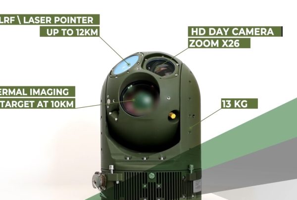
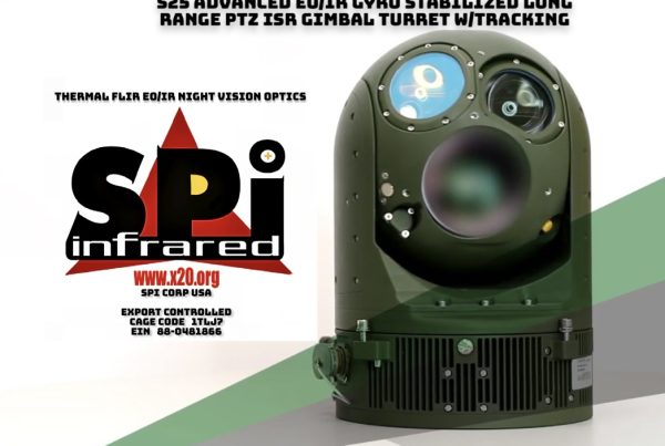
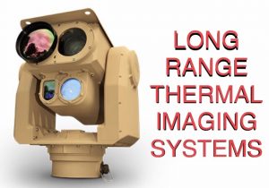
4.2.1B Long Range Thermal Imaging flir PTZ cameras
Long Range thermal imaging FLIR PTZ cameras are usually utilized for ultra long range human, and vehicular threat detection, identification and recognition, these robust heavy duty gimbal systems are typically used in borders, shorelines, coastlines and other critical areas for security and surveillance.
LONG RANGE FLIR THERMAL IMAGING PTZ CAMERA LINK
1x magnification; therefore, they do not bring objects into closer view. Accessories can be added to goggles to increase magnification and to con them to be more useful for surveillance. Different mounting configurations exist, but the most popular are headsets. Some goggles are water resistant and provide improved durability.
4.2.2 Image Intensifier Resolution
4-3. NVD Rifle Scope
I2 resolution is affected by the quality of the optical components as well as the performance of the I2 tube. High quality tubes combined with quality optical components can result in better image quality, and the highest quality tubes usually are reserved for the military. I2 resolution can be expressed using the Johnson Criteria, which is a commonly accepted standard that defines the resolution required to perform certain tasks or functions, such as to detect and recognize personnel and vehicles at a given distance.
The Johnson Criteria was originally developed in the 1950s to predict target detection, recognition, and identification. The Johnson Criteria is based on perceptual thresholds expressed in terms of line pairs. A line pair is equivalent to two adjacent pixels in a computer video display. The Johnson Criteria calls for the use of the U.S. Air Force (USAF) Resolution Target, shown in 4-5, which was developed in 1951. The resolution target models the probability of detection or recognition of targets in the field. Testing using the Johnson Criteria provides an accurate and consistent summary of a device’s resolution.
4-5. 1951 USAF Resolution Target
4-4. NVD Goggles
4.2.3 Photosensitivity
Photosensitivity is the ability to produce a detailed image under reduced illumination. When selecting an I2 device, photosensitivity in the NIR spectrum (700 to 1,100 nm) should be considered. At night, the percentage of energy in the NIR spectrum is much greater than in daylight. High photosensitivity in the blue or visible spectral regions is much less important in security applications than sensitivity in either the infrared or NIR spectrum. Higher photosensitivity results in a greater signal-to-noise ratio (SNR).
4.2.4 Signal-to-Noise Ratio
The SNR is defined as the amount of light or “signal” at the detector divided by the amount of static disturbance or “noise” present. This ratio is one of the best predictors of the low-light performance of an NVD. SNR is also related to the low-light resolution of the I2 tube. Higher SNR values correspond to clearer and more detailed images.
4.2.5 Blooming and Haloing
Gen 1 I2 NVDs are particularly affected by “blooming” or “haloing.” This distortion results when a small, bright source of light, such as a flashlight, is in the FOV of the I2 NVD. Blooming is a temporary loss of contrast in the image, and resembles an area that has been blotted out. Haloing occurs when there is a bright light source in the FOV that results in rings around the light source, 4-6. Gen 2 and 3 I2 devices have significantly reduced haloing and blooming effects.
4.3 Thermal Imager Considerations
4-6. Haloing Example
When acquiring thermal imagers, configuration, cost, and networking capabilities are important considerations. Thermal imaging cameras are most often found in fire service agencies. Their cost depends on their configuration, such as handheld, monoculars, or goggles.
4.3.1 Thermal Detector Configuration and Cost
Thermal detector configuration is an important consideration because it significantly affects cost. The terms “cooled” and “uncooled” refer to the differences in thermal imaging architecture as explained in Section 2. Cooled thermal imaging cameras are highly sensitive and very costly. Cooling the thermal detector is important for high-resolution imaging. While cooled thermal imaging cameras have better resolution and sensitivity, they are heavy and more expensive than uncooled thermal imaging cameras.
4.3.2 Networking Capability
Some thermal imaging cameras are wireless capable, utilizing Wi-Fi® and/or Bluetooth® technology. This allows them to be networked and provide real-time information to an emergency operations center that is remote from the incident scene. Transmitted images can also be stored as graphic files that retain all the characteristics of the thermal image.
4.3.3 Additional Thermal Imaging Considerations
Other performance metrics to consider before acquiring a thermal imager are detection range, resolution, and sensitivity:
- · Detection Range–Since digital zoom technology can be incorporated into thermal imaging cameras, detection ranges from 2 to 600 yards or more are achievable depending on the focal length of the lens. Without digital zoom, human detection range can be from 100 to 300 yards, depending on the type of imager;
- · Spatial Resolution–Thermal imaging sensor resolution can be measured in milliradians (mrad). Commercial thermal imaging resolution is generally in the 1.0 to 3.0 mrad range; and
- · Sensitivity–The sensitivity of a thermal imager measures the minimum temperature difference that the thermal imaging sensor can detect. This is typically 0.1 of a degree Fahrenheit for many devices, with some cooled devices as sensitive as 0.025 of a degree Fahrenheit.
4.4 Integrated Night Vision Considerations
Most of the considerations for INVSs are similar to those for I2 and thermal technologies, but with additions. Configuration is similar to I2, but the controls and methods for showing the additional sensors will differ. There are trade-offs for size, weight, and power needs for the processing system. A smaller, lighter, low power system may not possess the same features that a larger, heavier, more power consuming system will.
5. ACCESSORIES
The selection of accessories for any system is based on many factors that are determined by the intended application of the device. These factors may include weight, size, and observation distance that could conflict with one another. For example, in order to enhance an image, the system may need an accessory that increases the size and weight of the device. Accessories provide an advantage in that they can be added or removed as needed for a specific application. The following subsections provide brief descriptions of the various accessories that can be used with all NVDs (unless otherwise specified) to enhance operation.
5.1 Eyeguards
Eyeguards or eyecups are rubber shields mounted around the ocular lens of an NVD. An example can be seen in 5-1. Eyeguards enhance the operational security of an NVD by preventing the emission of stray light from the display. They also prevent facial reflections and help reduce eyestrain. Eyeguards can be retracted to accommodate eyeglasses.
5-1. Eyeguard
5.2 Lens Adapters
An objective lens collects available light, provides image magnification, and focuses the light on the sensor. Some of the more efficient NVD objective lenses have low magnification (5x or less), and are high-speed with an f-stop of 2 (f/2) or less. Lens adapters can be added to increase magnification. “Doubler” lens adapters, such as the one shown in 5-2, increase the lens magnification two to three times. Auxiliary lenses can increase magnification five times or more, but at the expense of reduced light gathering ability.
Thermal imaging cameras can use a doubler, but typically, optics are one of the more expensive components on a thermal imaging camera. Often a user will customize optics based on the desired mission, such as human activity detection at extended range. Doublers apply to both thermal FLIR imaging and I2 night vision devices
5.3 Camera Adapters
5-2. Doubler Lens Adapter
The ability to capture photographic images and video from NVDs is important to surveillance applications. A wide assortment of adapters for digital cameras, 35 mm cameras, CCTV, and video equipment is available for most NVDs. An adapter connects the filter threads of the camera lens to the NVD allowing the camera to take a photo of the display screen of the NVD. Adapters are available to fit a large variety of camera lenses.
5.4 NIR Illuminators
NIR illumination is an enhancing technology that uses three basic light sources—incandescent, LED, and laser—as described in Section 2.3. NIR illuminators can be added to I2 NVDs to enhance performance.
5.4.1 Dual Beam Laser Infrared Illuminator
Built-in, dual-beam laser infrared illuminators, such as the one shown in 5-3, allow adjustment for low or high beam illumination according to the environment and the application. Low beam is used for wide-angle illumination and high beam is used for pinpoint illumination.
5.5 Sacrificial Window
Sacrificial windows are attached to the front of the objective lens to prevent scratching and cracking. An example can be seen in 5-4. These barriers provide extra protection for the fragile objective lens without obstructing the view or reducing magnification.
5-3. Assault Rifle With Dual Beam Infrared Illuminator
5-4. Sacrificial Window
5.6 Magnetic Compasses
A magnetic compass provides a compass reading within the NVD display. The NVD user activates the compass illumination with a pressure switch. This illumination does not interfere with the NVD image.
5.7 Waterproof and Water-Resistant Night Vision Devices
Some NVD housings are designed to be waterproof. This accessory allows the device to be completely submerged without harming the internal optic or electronic systems. Demist shields also snap onto the eyepiece of a device to prevent condensation from forming on the optics.
5.8 Laser Range Finder
A laser range finder is a device that uses a laser beam to measure the distance to an object. It works by sending a laser pulse beam to the object and measuring the time it takes the beam to bounce off the object and return to the range finder. Laser range finders can be attached to I2 scopes to provide more accurate target definition in applications employing snipers.
5.9 Headgear
Headgear kits, such as the one shown in 5-5, come in various combinations, but typically consist of a headset that supports the device while it is being operated, one or more auxiliary lenses, an NIR illuminator, a camera adapter, and a case. The headset may either be a strap type that is worn directly on the head or a helmet mount. Headgear allows hands-free operation of I2 and thermal imaging cameras.
5-5. Headgear
APPENDIX A. DEFINITIONS
Definitions of terminology commonly used and/or associated with night vision technologies are provided below.
Automatic Brightness Control (ABC)–An electronic feature that automatically reduces voltage to the microchannel plate to keep the image intensifier’s brightness within optimal limits and protect the tube.
Binocular–The viewing of a scene through two eyepieces.
Black Spots–Cosmetic blemishes found in image intensifiers. Black spots in the image intensifier do not affect the performance or reliability of the device and are inherent in the manufacturing process.
Blooming–The momentary loss of the night vision image due to intensifier tube saturation by a bright light source. When bright light enters an I2, the entire scene becomes much brighter, “whiting out” objects within the FOV.
Bright-Source Protection (BSP)–The electronic function that reduces the voltage to the photocathode when an I2 device is exposed to bright light sources. Protects the image tube from damage and enhances its life.
C-Mount–C-mount lenses have a 1-inch mount diameter with a thread pitch of 32 threads per inch and focus 17.5 millimeters behind the rear lens element.
Commercial Specifications (COMSPEC)–Term used to describe image tube quality, testing, and inspection performed by the original equipment manufacturer (OEM).
Daylight Lens Cover–The lens cover, usually made of soft plastic or rubber, with a pinhole that allows a small amount of light to enter the objective lens of a night vision device.
Daylight Training Filter–The glass filter assembly designed to fit over the objective lens of a night vision device. The filter reduces light input to a safe level, and allows safe extended daytime use of the night vision device for training purposes.
Diopter–The unit of measurement used to define eye correction or the refractive power of a lens. Adjustments to an optical eyepiece accommodate for differences in individual eyesight.
Distortion–The undesirable change in the shape of an image resulting from imperfections in the optical or electronic components.
Emissivity–The physical property of a material to absorb and release heat energy. Emissivity is a dimensionless quantity between 0 and 1. High emitting surfaces are also good radiators and absorbers.
Equivalent Background Illumination (EBI)–The amount of light, measured in lumens per square centimeter, as seen when an I2 device is operating with no external light input. EBI varies with the temperature of an I2; the warmer the I2, the brighter the background illumination.
Eye Relief–The distance between the user’s eye and the eyepiece lens of an optical device at which the viewed scene can be clearly seen.
Field of View (FOV)–The size of the area that can be seen while looking through an optical device.
High Light Shutoff–An image intensifier protection feature that turns the system off during periods of extreme bright light conditions.
Light-Secure Eyeguard (Shuttered Eyeguard)–The rubber eyecup fitted to an eyepiece of a night vision device that incorporates a shutter that closes when not depressed by the user’s eye, thus preventing face glow that can compromise the user’s location.
Lux–A derived unit based on lumen, and lumen is a derived unit based on candela. One lux is roughly equivalent to a totally overcast day and 0.00001 lux is roughly equivalent to a totally overcast night with no moonlight.
Microchannel Plate (MCP)–The metal-coated glass disk that multiplies the electrons produced by the photocathode. Found only in Gen 2 and Gen 3 image intensifier systems, the MCP typically has between 2 and 6 million holes (or channels).
Military Specifications (MILSPEC)–The minimum acceptable requirements for products procured by the U.S. Department of Defense. Use of the term MILSPEC indicates that the product meets applicable military specifications.
Monocular–A device consisting of a single-eyepiece. Image intensifier monoculars are also known as pocket scopes.
Photocathode–The input surface of an image intensifier tube that absorbs light energy (photons) and in turn releases electrical energy (electrons) in the form of an image.
Photocathode Sensitivity–The photocathode sensitivity is a measure of how well the image intensifier tube converts light into an electronic signal so it can be amplified.
Resolution–The term resolution is used to express the level of detail that can be captured by a sensor, camera imager, or camera, or displayed by a video monitor. Resolution applies to the horizontal, vertical, and color characteristics of the details in an image.
Scintillation–The faint, random, sparkling effect throughout the image area, also known as electronic noise. Scintillation is a normal characteristic of an image intensifier device.
Courtesy of DHS